Measuring the profile accuracy of turbine impellers after machining is crucial to ensure optimal aerodynamic performance and mechanical reliability. The complex geometry and high precision demands of turbine impellers make accurate profile measurement essential for quality assurance and performance validation. This article explores the fundamental concepts, measurement techniques, equipment, workflows, and latest innovations in turbine impeller profile measurement, providing a comprehensive guide for engineers and quality control professionals.
Basic Concepts of Profile Tolerance
Profile tolerance is a key principle in geometric dimensioning and tolerancing (GD&T) that defines the allowable deviation of a manufactured part’s surface or curve from its ideal, nominal shape. This tolerance ensures that critical components, such as impeller blades, maintain precise surface geometry essential for optimal aerodynamic performance and balance. The tolerance zone is conceptualized as a series of imaginary spheres along the nominal profile, each with a diameter equal to the specified tolerance. The actual surface must lie within these spheres to be acceptable, providing a three-dimensional control of shape beyond simple linear measurements.
There are two main types of profile tolerance: line profile and surface profile. Line profile tolerance controls the shape of a specific curve or edge, which is vital for features like blade edges where aerodynamic efficiency depends on accurate curvature. Surface profile tolerance applies to the entire surface, ensuring the overall form remains within the allowable limits to maintain smooth airflow and balance. Strict adherence to these tolerances is crucial during manufacturing and quality inspection, as even minor deviations can cause imbalance, vibration, and reduced performance in high-speed rotating impellers.
Structural Characteristics of Turbine Impellers
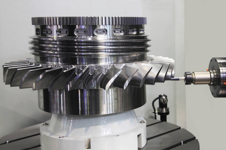
Turbine impellers are critical components in turbines, designed to efficiently convert fluid energy into mechanical work. Their structural design balances aerodynamic performance with mechanical strength and durability. The main structural elements include roots, blades, and shrouds or crowns, each playing a vital role in the overall function and integrity of the impeller.
The root forms the base of the impeller and serves as the connection point between the blades and the central hub, ensuring secure attachment and transfer of mechanical loads. The blades themselves are aerodynamically shaped with complex curves to optimize fluid flow and maximize energy conversion efficiency. These blades are subjected to intense stresses and require precise manufacturing to maintain performance. The shrouds or crowns form the outer rim of the impeller, providing structural support and helping to minimize blade vibration and stress concentrations. The overall geometry of turbine impellers involves intricate curved surfaces, arcs, and end faces, which make profile measurement and quality control highly challenging but essential for ensuring balanced rotation and long-term reliability.
Common Methods for Measuring Turbine Impeller Profile
Accurate measurement of turbine impeller profiles is crucial to ensure their aerodynamic efficiency and mechanical reliability. Given the complex geometry of impeller blades and surfaces, manufacturers rely on advanced metrology techniques to precisely capture and analyze the shape of these components. Several measurement methods, including Coordinate Measuring Machines (CMM), optical profilometry, and 3D scanning, are widely used to meet stringent quality standards in turbine production.
Coordinate Measuring Machine (CMM) Method
Coordinate Measuring Machines offer high-precision, automated surface measurements by capturing discrete points across the impeller profile and comparing them against the original CAD models. The process begins with establishing a measurement coordinate system aligned with the CAD design, followed by securing the impeller in a precision fixture. Contact or laser probes then scan the surface to generate a detailed point cloud. Specialized software such as PC DMIS or Geomagic Control processes this data to calculate deviations from the nominal profile. The major advantages of CMM include exceptional accuracy even on complex curved surfaces, automation that reduces human error, and suitability for a wide range of impeller sizes.
Optical Profilometry
Optical profilometry utilizes non-contact laser triangulation combined with high-resolution imaging to reconstruct the 3D surface profile of the impeller. During measurement, reference lines are projected onto the impeller’s surface and captured by cameras. Advanced software then reconstructs the 3D shape and computes profile tolerance deviations. This method is especially advantageous for delicate or soft materials since it avoids surface damage. Additionally, optical profilometers can measure surface roughness and waviness simultaneously, providing a comprehensive surface quality assessment.
3D Scanning Methods
3D scanning technologies, such as blue light scanners, offer rapid and detailed data acquisition by capturing dense point clouds of the impeller surface. The impeller is placed on a scanning platform, and the scanner collects comprehensive surface data in a short time. The scanned data is then compared with CAD models to identify geometric deviations. This technique is highly effective for large impellers and complex geometries, enabling detailed surface representation that supports reverse engineering and in-depth profile analysis. Its speed and accuracy make it a valuable tool for quality control and design validation in turbine manufacturing.
Tools and Equipment for Turbine Impeller Profile Measurement
Measuring the precise profile of turbine impellers requires specialized tools and equipment designed to handle complex geometries with high accuracy and repeatability. These instruments not only capture critical dimensional and surface data but also ensure stable and consistent measurement conditions. The choice of equipment significantly affects the reliability of profile assessments, impacting overall impeller performance and lifespan. Key tools include Coordinate Measuring Machines (CMM), optical profilometers, and customized fixtures for secure clamping.
Coordinate Measuring Machines (CMM)
Coordinate Measuring Machines are essential for accurately measuring geometric dimensions, shapes, and positional tolerances such as straightness, flatness, circularity, cylindricity, and positional accuracy. Popular models like ZEISS PRISMO, Mitutoyo Crysta-Apex, and Hexagon CMMs provide multi-axis probe movement, allowing comprehensive scanning of complex impeller surfaces. Their high repeatability and precision make CMMs indispensable for verifying that turbine components meet stringent design specifications, especially for critical features affecting aerodynamic and mechanical performance.
Optical Profilometers
Optical profilometers are widely used to measure surface roughness, waviness, and detailed profile contours without physical contact. Leading brands such as Zeiss, Mitutoyo, and Keyence offer instruments with high resolution and fast scanning capabilities, making them suitable for inspecting delicate or sensitive impeller surfaces. These tools help identify microscopic surface defects or irregularities that could impact flow efficiency or cause premature wear, ensuring the impeller’s surface quality meets operational requirements.
Fixtures and Clamping Devices
To achieve accurate and repeatable measurements, impellers must be securely held in place during inspection. Fixtures and clamping devices are designed to stabilize the component and maintain consistent reference points throughout the measurement process. Given the complex shapes of turbine impellers, these fixtures often require customization to adapt to specific blade geometries and sizes. High precision and stability in clamping ensure minimal movement or distortion, which is critical for obtaining reliable measurement data across multiple inspection cycles.
Workflow for Turbine Impeller Profile Measurement
Measuring the profile of turbine impellers involves a systematic workflow to ensure precise, repeatable, and reliable results. This process integrates careful preparation, accurate data acquisition, and thorough analysis, all aligned with the impeller’s design specifications. Proper execution of each phase is critical for validating manufacturing quality, ensuring aerodynamic efficiency, and maintaining mechanical integrity. The workflow typically encompasses establishing reference systems, selecting appropriate measurement tools, collecting detailed surface data, and performing comprehensive profile analysis.
Preparation Phase
The first step in the workflow is establishing a reference coordinate system that precisely aligns the measurement setup with the impeller’s CAD design. This alignment ensures that all data collected correspond accurately to the intended geometry. Selecting the correct fixtures is equally important; they must provide secure and stable clamping to prevent any vibration or movement during measurement, which could otherwise distort results. Additionally, choosing the right probe type—whether contact or non-contact—depends on the impeller’s surface condition and measurement requirements, balancing accuracy and surface preservation.
Data Acquisition
During this phase, dense point cloud data of the impeller surface are collected using Coordinate Measuring Machines (CMM), 3D scanners, or optical profilometers. High-density data capture allows detailed mapping of complex blade contours and surfaces. Following data collection, preprocessing steps such as noise filtering and data smoothing are applied to enhance measurement accuracy by removing artifacts and inconsistencies that could affect analysis outcomes.
Profile Analysis
In the final stage, a theoretical model or nominal profile is generated directly from the CAD design for reference. The measured data points are then compared against this nominal profile to calculate deviations, identifying any areas where the impeller’s surface falls outside allowable tolerance zones. The results are compiled into detailed reports that quantify profile deviation and assess compliance with stringent design and manufacturing specifications. This comprehensive analysis supports quality control and guides any necessary corrective actions in the production process.
Key Considerations for Accurate Measurement
Achieving precise and repeatable measurements of turbine impeller profiles requires careful attention to various environmental, procedural, and technical factors. Due to the complex geometry and tight tolerance requirements of impellers, even minor measurement inconsistencies can lead to significant quality deviations. Therefore, establishing a robust measurement environment and workflow is essential for ensuring high fidelity in both data acquisition and analysis. The following considerations are crucial for maintaining accuracy throughout the profile measurement process.
Environmental Controls
Controlling environmental conditions is fundamental for precision measurement. Variations in temperature can cause thermal expansion in both the impeller and the measuring equipment, leading to distorted readings. Therefore, measurement rooms should be maintained at a constant temperature (typically around 20 °C) and humidity to ensure dimensional stability. In addition, for optical profilometry and 3D scanning systems, proper lighting control is essential. Ambient light fluctuations or reflections can interfere with image capture and affect surface reconstruction accuracy, especially on reflective or curved impeller surfaces.
Reference Datum Management
Accurate profile measurement depends on reliable and consistent datum features. The datum system must correspond precisely with those defined in the CAD model to avoid misalignment during comparison. This ensures that profile deviations are interpreted correctly relative to the design intent. Additionally, regular calibration of measurement equipment, including probes, scanners, and fixtures, is necessary to preserve measurement integrity. Any drift in calibration can lead to systematic errors, compromising the validity of the collected data.
Data Integrity and Processing
High-quality data acquisition hinges on capturing a complete and well-distributed point cloud that fully covers the impeller’s critical surfaces. Sparse or uneven point distribution can mask defects or exaggerate deviations. Selecting suitable measurement software is also key—tools like Geomagic Control, PC DMIS, or PolyWorks offer robust features for profile comparison and tolerance analysis. Before beginning analysis, it is essential to validate the data set for completeness and correctness, ensuring no missing areas or noise artifacts compromise the results. Careful data handling ensures the final evaluation reflects true manufacturing quality and performance readiness.
Advances and Optimization in Profile Measurement
As turbine impellers become more geometrically complex and tolerance requirements tighten, traditional measurement techniques alone are often insufficient to meet production efficiency and accuracy goals. Recent technological advances in metrology have introduced a new era of automation, sensor integration, and standardization. These innovations not only enhance measurement precision and reduce labor costs, but also support scalable, data-driven quality control. Below are key developments driving the optimization of impeller profile measurement processes.
Automation
Automation significantly improves the efficiency and repeatability of impeller measurements. Automated fixtures and robotic systems can position impellers with high consistency, minimizing human error and setup variability. In parallel, AI-powered algorithms are being deployed to process point cloud data more intelligently—automatically filtering noise, filling in missing areas, and identifying deviations with minimal operator input. These advancements reduce the time required for both measurement and analysis, making real-time quality control feasible on high-throughput production lines.
Multi-Sensor Fusion
Modern measurement systems increasingly rely on multi-sensor fusion to capture comprehensive geometric data. By integrating data from coordinate measuring machines (CMMs), optical profilometers, and 3D scanners, engineers gain a more complete understanding of an impeller’s surface characteristics. This approach compensates for the limitations of any single method and enhances robustness. Furthermore, some systems now include real-time feedback loops that adjust scanning paths dynamically based on surface curvature or detected deviations, ensuring optimal data collection even for complex blade geometries.
Standardization and Best Practices
The adoption of international standards such as ISO 1101 (geometrical tolerancing) and ASME Y14.5 ensures consistent interpretation of profile tolerances across teams and organizations. Implementing standardized workflows—from fixture setup and coordinate alignment to deviation reporting—reduces variability in results between operators and measurement stations. These best practices enable more reliable comparisons over time and across production batches, fostering traceability and continuous improvement in impeller manufacturing quality.
Case Studies
Profile measurement is vital for ensuring the precision, balance, and performance of turbine impellers, especially in high-demand sectors such as aerospace and power equipment. In one case involving aviation turbine blades, coordinate measuring machines (CMMs) and laser scanning technologies were used to control profile deviations within ±0.1 mm. The high-resolution data allowed engineers to identify consistent deformation in thicker root sections, leading to informed design corrections and improved manufacturing consistency. This precise feedback loop minimized rework and enhanced the overall structural reliability of the blades.
In another application, 3D structured light scanning was used to reverse-engineer an impeller with no existing digital model. Engineers captured high-density surface data, reconstructed the CAD profile, and validated new components against these digital references. The process not only enabled accurate replication but also supported tighter tolerance control and more efficient assembly workflows. These cases highlight how modern measurement technologies serve as both inspection tools and enablers of design optimization and lifecycle extension in complex turbomachinery.
Conclusion
Accurate profile measurement of turbine impellers after machining is essential for maintaining aerodynamic efficiency and mechanical integrity. Utilizing advanced measurement methods like CMM, optical profilometry, and 3D scanning, combined with standardized workflows and automation, ensures precise and reliable profile control. Future trends in AI and multi-sensor integration will further enhance measurement capabilities, supporting high-performance turbine impeller manufacturing and assembly.


