Turbine impellers are critical components in jet engines, turbines, and turbomachinery—shaping airflow, optimizing thermodynamic efficiency, and determining lifespan. With rising performance demands, manufacturing methods have evolved. CNC machining continues as the hallmark of precision and consistency, ideal for high-volume, high-strength alloys. Meanwhile, 3D printing unlocks complex geometry, offering freedom to design internal cooling channels and organic shapes once unattainable with subtractive methods. However, each technology comes with trade‑offs: CNC provides unmatched surface finish and material properties but wastes material; 3D printing excels for customization, yet struggles with finish, tolerance, and certification. This article will explore both technologies in depth: how they work, their advantages and limitations in impeller contexts, material compatibility, economics, real examples like Siemens gas turbine blades, and future trends—including hybrid manufacturing and AI‑driven CNC. Ultimately, we’ll assess suitability to help you decide which path fits your specific impeller needs.
What Is CNC Machining?
Computer Numerical Control (CNC) machining is a subtractive manufacturing process where pre-programmed toolpaths control high-precision, multi-axis machine tools to remove material from solid billets. These toolpaths—created using CAD/CAM software—guide processes like milling, turning, and drilling with exceptional accuracy, often achieving tolerances as tight as ±0.01 mm and surface finishes below Ra 0.5 µm. Especially suited for aerospace components such as impellers, CNC machining can handle advanced materials like nickel-based superalloys, titanium alloys (e.g., Ti‑6Al‑4V), and stainless steel with high repeatability, making it ideal for both prototyping and batch production.
The CNC machining workflow involves several stages. It begins with toolpath programming, followed by strategic fixturing and multiple setups to access all part geometries. Machining progresses through roughing, semi-finishing, and precision finishing steps. Post-processing—such as deburring, polishing, and heat treatment—ensures the final part meets strict mechanical and surface standards. Despite its precision and reliability, CNC machining comes with limitations like material waste, high tooling costs, and challenges in creating internal passages or conformal cooling structures that are more easily achieved through additive manufacturing.
Benefits of CNC machining for turbine impeller machining
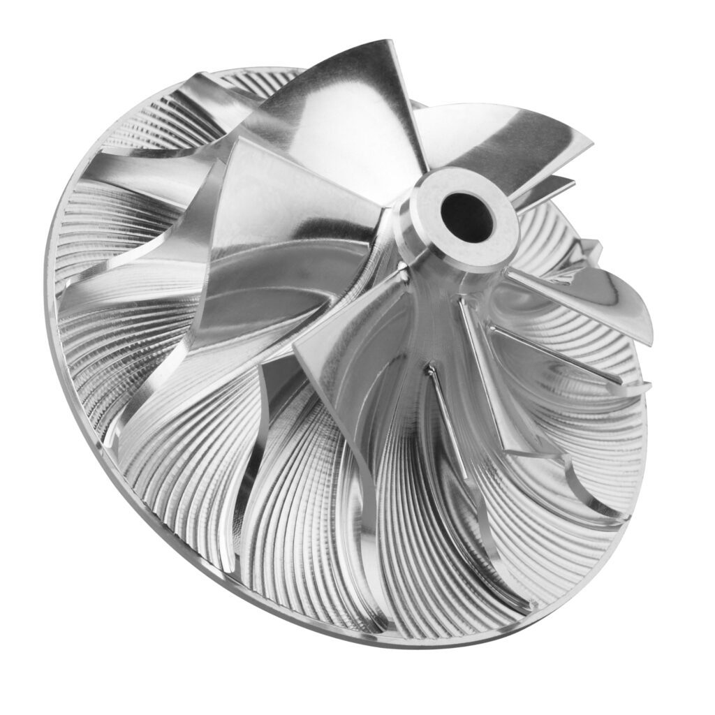
Turbine impellers demand extreme precision, strength, and reliability due to their high-speed rotation and operation under harsh conditions. CNC machining is ideally suited for manufacturing these critical components, offering a blend of tight tolerances, material compatibility, and repeatable quality that few other processes can match. Below are the key benefits CNC machining brings to impeller production:
Exceptional Dimensional Accuracy
CNC machining achieves tight tolerances—down to ±0.01 mm—ensuring that every blade and contour of the impeller matches design intent. This precision is essential for aerodynamic balance and performance in high-speed turbine systems.
Superior Surface Finish
The process delivers fine surface roughness values (as low as Ra < 0.5 µm), minimizing post-processing and improving flow efficiency. This is particularly important for blade surfaces, where smoother finishes reduce turbulence and energy losses.
High Repeatability for Batch Production
Once programmed, CNC machines can produce identical parts with minimal variation, making them ideal for producing multiple impellers with consistent quality. This ensures reliability across turbine units and simplifies downstream assembly and balancing.
Advanced Material Capability
CNC machining reliably handles high-performance alloys like nickel-based superalloys, Ti‑6Al‑4V titanium, and stainless steels. These materials are essential for turbine environments where temperature resistance, fatigue strength, and corrosion resistance are non-negotiable.
Flexibility for Design Changes
CNC programming allows for relatively fast adjustments in design without new tooling, which is advantageous during prototype development or performance optimization phases.
Overall, CNC machining offers a robust solution for meeting the strict requirements of turbine impeller manufacturing, balancing precision, durability, and efficiency.
Factors to consider when CNC machining turbine impeller
While CNC machining offers high precision and material versatility, several critical considerations must be accounted for when applying it to turbine impeller manufacturing. These factors can impact production cost, design feasibility, and overall efficiency. Understanding these challenges is key to optimizing the process.
Material Waste and Cost Efficiency
CNC machining is a subtractive process—material is removed from a solid billet to create the final shape. This results in significant material waste, particularly when using expensive superalloys. The generated chips may be recyclable, but the inefficiency can raise overall production costs.
Geometric Limitations
Certain design features, such as internal cooling passages or conformal geometries, are difficult or impossible to achieve with traditional CNC techniques. These complex internal structures often require multiple setups, custom tooling, or may need to be redesigned entirely for manufacturability.
Tooling Costs and Wear
Machining hard-to-cut materials like Inconel or titanium requires specialized, often coated, cutting tools that are costly and wear quickly. Frequent tool changes and maintenance can add to both cycle time and operational expenses.
Extended Machining Time
Achieving the necessary precision and surface finish for turbine impellers—especially with multi-axis machining—involves long cycle times. This includes roughing, semi-finishing, and high-precision finishing stages, each of which contributes to extended lead times and higher labor or machine costs.
Multiple Fixturing and Setups
To access all surfaces of the impeller, especially in complex 5-axis geometries, multiple workholding setups are required. Each setup increases the potential for misalignment and introduces added complexity into the workflow.
Considering these factors early in the design and planning phase helps mitigate challenges and ensures CNC machining remains a viable and efficient method for producing high-performance turbine impellers.
CNC machining turbine impeller workflow
Manufacturing a turbine impeller using CNC machining involves a structured, multi-step process that balances precision, efficiency, and repeatability. Each stage—from digital design to post-processing—plays a vital role in delivering a high-performance component that meets strict aerospace or energy-sector standards.
Toolpath Programming
The workflow begins with defining precise toolpaths using CAD/CAM software. These paths dictate how the machine moves, starting from roughing large volumes of material to intricate finishing passes. Special attention is given to complex blade contours and root fillets, ensuring optimal surface finish and accuracy.
Fixturing and Setups
Due to the impeller’s complex geometry, multiple setups are typically required. Custom fixtures or 5-axis workholding systems are often employed to securely position the part for complete access, minimizing vibration and ensuring repeatability across batches.
Step-by-Step Machining
The machining itself is performed in stages:
- Roughing removes the bulk of excess material.
- Semi-finishing brings the part closer to net shape.
- Finishing achieves tight tolerances and surface finishes (e.g., Ra < 0.5 µm), particularly important on aerodynamic surfaces like blades and hubs.
Post-Processing
After machining, components undergo secondary processes such as deburring, polishing, and heat treatment. These steps ensure compliance with mechanical property requirements and dimensional tolerances, particularly when dealing with superalloys or high-stress environments.
Following this workflow ensures a streamlined production process, delivering precision turbine impellers that meet stringent industry specifications.
What Is 3D Printing?
Metal additive manufacturing, commonly known as 3D printing, is a cutting-edge process that fabricates parts layer-by-layer directly from digital CAD models. Techniques such as powder bed fusion (including Selective Laser Sintering—SLS—and Selective Laser Melting—SLM) and direct energy deposition (DED) precisely fuse metal powders or wire feedstock to build complex geometries that would be difficult or impossible to achieve through traditional methods.
This layer-wise approach enables the creation of intricate internal features like cooling channels and lattice structures within turbine impellers. 3D printing also offers rapid prototyping capabilities and reduces material waste compared to subtractive processes. After printing, parts often undergo post-processing steps such as heat treatment, hot isostatic pressing (HIP), and CNC finishing to achieve the necessary mechanical properties and surface quality required for demanding aerospace and industrial applications.
3D printing’s strengths in turbine impeller machining
Additive manufacturing has emerged as a powerful alternative to traditional subtractive methods, especially for complex components like turbine impellers. By building parts layer by layer directly from CAD designs, 3D printing unlocks unique advantages that improve design freedom, reduce material waste, and speed up the production cycle—making it especially effective for low-volume or highly customized impeller fabrication.
Complex Geometry Freedom
Enables the creation of intricate internal cooling channels, lattice structures, and conformal features that are extremely difficult or impossible to achieve with CNC machining.
Minimal Material Waste
As a near-net-shape process, 3D printing uses only the material required for the part, with powder recovery options that further reduce waste and cost.
Rapid Prototyping & Small Batch Efficiency
Without the need for custom tooling or fixtures, design iterations can be printed quickly—ideal for R&D, prototype validation, or short-run production.
Cost-Effective for Low Volumes
Avoids the high upfront costs of CNC tooling and workholding setups, significantly reducing unit cost for small production runs or one-off parts.
These benefits make 3D printing an attractive option for innovative turbine impeller designs, especially in aerospace and advanced energy applications where performance and weight reduction are critical.
3D printing’s Drawbacks in turbine impeller machining
While metal 3D printing offers substantial design flexibility and efficiency for turbine impellers, it also presents notable limitations that must be carefully considered. These drawbacks primarily concern surface quality, dimensional precision, material properties, and the need for extensive post-processing—all of which can impact performance and cost-effectiveness in demanding turbomachinery applications.
Surface Roughness Challenges
As-printed surfaces often exhibit high roughness (typically Ra > 5–10 µm), which is unsuitable for aerodynamic impeller blades without additional finishing such as CNC polishing or abrasive flow machining.
Dimensional Inaccuracy
Warping, residual stress, and thermal shrinkage during layer-by-layer building can cause deviations of ±0.05–0.1 mm, affecting blade alignment and impeller balance.
Material and Certification Barriers
Limited alloy availability (e.g., fewer options for high-temperature superalloys) and inconsistent microstructures can make it difficult to meet aerospace-grade mechanical properties and certification standards.
Post-Processing Dependency
Most 3D printed impellers require significant downstream operations such as heat treatment, hot isostatic pressing (HIP), and CNC finishing to achieve final dimensional and structural integrity.
These challenges mean that while 3D printing is a valuable tool for impeller prototyping and design exploration, it often must be integrated with traditional processes to meet full-scale production and performance requirements.
3D Printing Turbine machining Workflow
The manufacturing of turbine impellers using 3D printing—also known as metal additive manufacturing—follows a structured workflow to ensure complex geometries are achieved with high performance and structural reliability. From digital modeling to post-processing, each step is critical to meet the stringent demands of turbomachinery applications.
Model Preparation
Engineers begin by designing the impeller in CAD, often incorporating advanced features such as internal coolant channels or lattice structures. These geometries are then optimized for additive manufacturing, including support generation and orientation setup, to ensure build success and efficiency.
Printing
The part is fabricated layer-by-layer using metal additive processes such as Powder Bed Fusion (PBF) or Direct Energy Deposition (DED). These technologies enable high design freedom and the creation of intricate shapes that are difficult or impossible to machine conventionally.
Post-Print Processing
Once printing is complete, the impeller typically undergoes thermal treatments like stress relief and Hot Isostatic Pressing (HIP) to enhance material density and mechanical strength. CNC finishing is often applied to critical surfaces such as blade edges and mating faces to meet precision and surface finish requirements.
Final Quality Inspections
The finished impeller is subjected to rigorous inspections, including dimensional measurement, surface finish analysis, and non-destructive testing (e.g., CT scanning or dye penetrant testing), ensuring compliance with aerodynamic and material standards for turbine applications.
This hybrid workflow enables the production of highly customized, performance-optimized impellers while maintaining the engineering rigor required in aerospace and energy sectors.
Direct Comparison: CNC vs. 3D Printing
When choosing between CNC machining and 3D printing for turbine impeller production, it’s essential to evaluate their capabilities across key criteria—ranging from material compatibility and geometry complexity to production economics and sustainability.
| Criteria | CNC Machining | 3D Printing (Additive Manufacturing) |
| Material Compatibility | Extensive material support, including Inconel, titanium, aluminum, and stainless steels. Proven for aerospace-grade alloys. | Increasing material options, such as stainless steel, Inconel, and Ti-6Al-4V. Some alloys still lack validation for critical use. |
| Production Volume | Highly cost-effective at medium to high volumes (typically 100+ units); tooling and setup costs are amortized. | Ideal for low-volume production (<50 units), prototyping, and custom or iterative design cycles. |
| Part Complexity | Suited for simple-to-moderate geometries; excels at external contours and accessible internal features. | Best for complex internal channels, lattice structures, and topology-optimized designs that are hard to machine. |
| Dimensional Accuracy & Finish | Delivers high precision (±0.01 mm) and fine surface finishes (Ra < 0.5 µm) after polishing. | Offers moderate accuracy (±0.05–0.1 mm) and rougher finishes (Ra 5–10 µm), typically requiring CNC post-processing. |
| Lead Time & Costs | High upfront investment in programming, fixtures, and tooling; unit costs drop significantly with volume. | Minimal setup; higher per-part cost but very fast turnaround for small batches or urgent jobs. |
| Sustainability | Generates significant material waste in the form of metal chips; energy-intensive setup. | Near-net-shape builds result in minimal waste; excess powder is often reusable, enhancing material efficiency. |
Hybrid Manufacturing: Best of Both Worlds
In advanced turbine impeller production, hybrid manufacturing is emerging as a transformative approach by merging the benefits of additive manufacturing (AM) and CNC machining. This integrated process leverages the design flexibility of AM—especially for internal features like cooling channels—while ensuring final dimensional precision and surface finish through CNC. Hybrid systems, which often combine both capabilities in a single machine, allow for efficient workflows, reducing both waste and production time.
Hybrid Pathways in Practice
- Near-net-shape AM → CNC finish
Additive builds the basic form close to final geometry; CNC machining brings critical dimensions and surfaces to spec.
- DED core structures → CNC blade surfaces
Directed Energy Deposition (DED) quickly forms impeller cores, while blades—requiring smooth finishes and tight tolerances—are CNC machined afterward.
- Integrated toolpaths in hybrid machines
Advanced hybrid machines can switch seamlessly between printing and milling within a single program, eliminating the need for re-fixturing.
Key Advantages
- Minimized material waste and fixturing steps
Material is only added where needed, and fewer setups reduce alignment errors and manual labor.
- Enhanced design capability
Enables the creation of complex, conformal cooling passages while still achieving tight tolerances on critical surfaces.
- Reduced lead time
Combining processes into one system shortens production cycles, particularly for high-performance, geometrically intricate components.
Points to Consider
- Higher initial investment
Hybrid machines are expensive and require significant capital outlay, making them more suitable for high-value, complex parts.
- Process integration complexity
Seamlessly combining AM and CNC demands advanced CAM software and experienced operators to manage toolpath transitions and thermal stresses.
Hybrid manufacturing offers an optimal solution for turbine impellers that demand both intricate internal geometries and aerospace-grade precision—blending creativity with capability in a unified production strategy.
Conclusion
Choosing between CNC machining and 3D printing for turbine impellers ultimately depends on part complexity, production scale, materials, and budget. CNC remains unbeatable for high precision, large volume, and conventional alloys. 3D printing shines in prototyping and complex geometry. The future lies in hybrid manufacturing, combining additive’s geometric freedom with CNC’s precision to produce turbine impellers that exceed today’s performance standards.


